Today Scott and I did some tests on pulsing a solenoid to vary flow rate which gave encouraging results. Eventually I would like to work out a relationship for flow rate vs. duty cycle, but today all we did were some basic tests to determine if we could get the flow rate to change with duty cycle and by how much.
We used a frequency of 30Hz which I read worked for Armidillo, and tested 4 duty cycles between 25 and 100 percent with an initial tank pressure of 500PSI. For each duty cycle we filled the tank with 2L of water and ran three tests measuring the flow rate over 10 seconds.
Initially we got some quite inconsistent results which can be seen in this table:
Frequency (Hz)
30
Duty Cycle
Water Output (g)
1st 10 s
2nd 10 s
3rd 10 s
0.25
303
224
147
0.5
299
226
276
0.75
312
369
290
1
294
146
337
When testing we could see air come out with the water which we thought would have affected the results. We have encountered this problem before but it hasn't really affected anything until now. My theory is that because the fill cart is still connected to the setup and contains air initially at the same pressure as the tank, as the pressure in the tank drops air is injected into the main 4 way cross as the pressure in the tank drops. We added a ball valve at the cross to isolate the fill cart which both eliminated the air coming out with the water and made the results much more consistent.
Results after adding in the isolation valve can be seen here:
With valve addition
Frequency (Hz)
30
Duty Cycle
Water Output (g)
1st 10 s
2nd 10 s
3rd 10 s
0.25
180
174
1045
0.5
210
329
1276
0.75
186
485
454
1
413
535
488
There is still some inconsistency in the first test, but I think this can be explained by the fact that for the first few seconds after a new fill only air comes out as there is air in the lines.
We found that for the low duty cycles every now and again we got these huge flow rates that was even greater than the flow rate when the solenoid was fully on. We noticed that these coincided with a pocket of air coming out. Scott and I had a few ideas which could explain this. Firstly, for the low duty cycles we could actually hear the solenoid opening and closing as opposed to the later tests where no could could be heard from the solenoid. One theory is that the mass spring system which is oscillating inside the solenoid has its natural frequency close to our test frequency of 30Hz and that the air perturbs the system enough to make it unstable which results in the poppet travelling much more in the open direction than is possible due to the electromagnetic force alone. If this is the case we might want to change the duty cycle as a sudden increase in flow rate wont be good.
It is interesting that for the low duty cycles the solenoid was actually oscillating. I think we will want to make it so that it doesn't if we can. This will probably mean increasing the frequency.
The results look slightly erratic but that the 2nd and third for both runs are good, and would be better if it wasn't for the crazy high flow rate of the low duty cycles.
On another note it is clear now that using a consumable catalyst isn't going to provide the lifetime I need for the hovering vehicle.
As I have previously said I would greatly prefer to buy peroxide rather than make it myself, but the problem is suppliers that will sell to individuals are few and far between. The lack of success in the consumable catlyist department has motivated me to push a little harder and I have now found a supplier and last week I placed an order for 20L of %90 rocket grade peroxide, which should arrive next week.
With this I swill be able to travel the well worn path of silver mesh catlyist. I am slightly disappointed, as I really liked the idea of a granular catlyist but we learnt a huge amount and other than the time lost, I hadn't invested a large amount of money if equipment specific to the granular catlyist.
Monday 26 March 2012
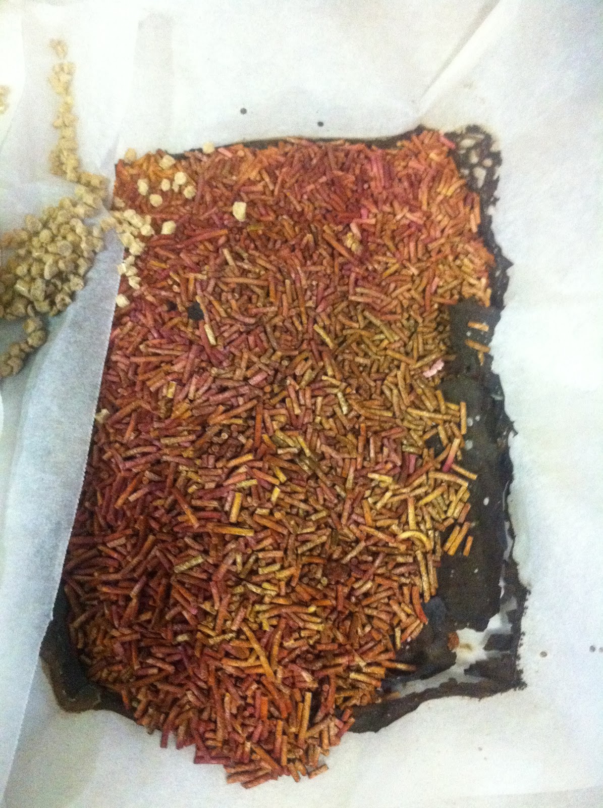
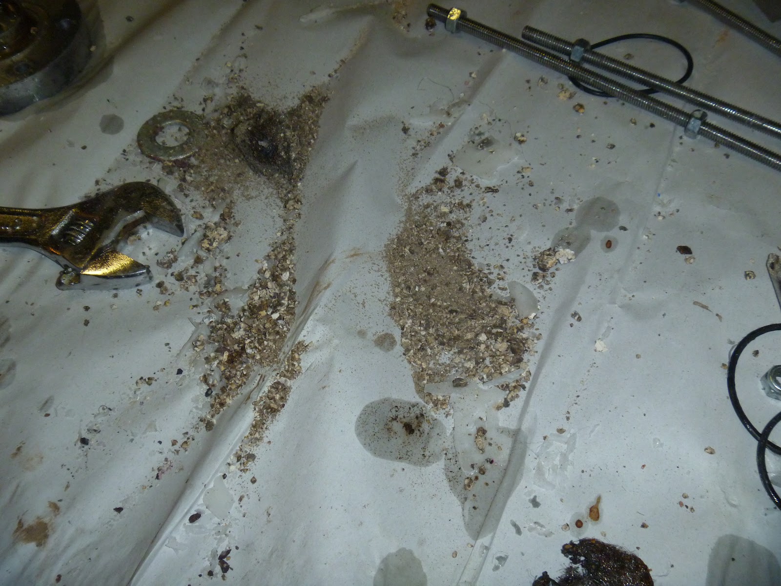
On Sunday we conducted a series of tests. I had been planing on trying out a new type of catalyst media (molecular sieve) I sourced, however I discovered when preparing it that the permanganate doesn't actually get absorbed into the sieve, only the water in the solution (possibly). The result is that you have a material that looks purple but doesn't actually contain any permanganate. Its funny that the sieve does its job exactly, it absorbs what it was designed to (water) and not other stuff.
As it turns out desicants can work through absorption or adsorption, which are two different things entirely, although they both have the same result. The former is actually a chemical process (the desicant changes its chemicial structure) where the latter is purely a physical process (like a sponge) relying on surface area alone. For example when sodium hydroxide "absorbs" carbon dioxide from the air, and its chemical formula changes (not sure what to) to include an extra CO2.
The sieve actually works by absorption (chemcial one), which explains why there are different types of sieve that absorb different sized molecules. In addition, when in a solution potassium permanganate is ionic, which also significantly complicates things. I am not sure I really understand extelly why the zeolite wouldent absorb the solution because its not based on the size of the molecules, but I do know that one of the ways in which zeolite absorb is via ion exchange, so I believe it might have absorbed the potassium or the manganese depending on if it is - or +. They seem to be usually anionic, I think because they are usually used to dry hydrocarbon gasses, which means it would be absorbing the potassium, and leaving manganese. I did notice some discolouration in the media after impregnation, which could posibly be manganese, although I am not sure if you can just get manganese from a manganese ion, you would have to get something with it (manganese dioxide for example). See the bellow photos for a comparison between the clay (Above or possibly left) which is a deep purple and the bellow molecular sieve pellets (bellow or right) which are almost brown.
So I had been planing on testing some 3 and 10 angstroms sieve, but couldn't do that because I knew that the permanganate, if indeed there was any on it would just have gotten washed away resulting in a nice fountain of uncatalised peroxide.
The other thing we were testing was the new engine and that data acquisition system. It is a significant improvement over the old bi-prop engine we were using, both in the time it took to change catlyist and the smoothness of the exhaust due to the post decomposition chamber. I dident time it but I think that between the first and second tests we changed catlyist in about 15 minutes and allot of that time was taking photos.
We got some nice data from the acquisition system, although there were some issues with reliability. It is unfortunate that on the third test (the only one to be successful) the data cut out a few seconds in. I have yet to identify what the cause is but I have noticed that sometimes the readings will go to 5V and stay there. I think this may be because of communication issues between the Arduino and computer. With the lab view firmware on it, communication is at 115200 baud. I used to run it at 9600, so I am not surprised that there are communication issues. The problem is I think it needs to talk this fast in order for lab view to get all the information it needs. I really need to just use a NI DAQ. I have one I can use (its Jamie's) so I might give that a try and see if that fixes my issues. If i doesn't then the problem must be in the usb server or wifi link.
I could convert the voltage reading from the pressure transducer into pressure just from the manufactures data, but as I changed the gain on the load cell amplifier I can't convert the load cell voltage into force without putting some weight on it and taking measurements, which I haven't had time to do. Also I am not sure what units the time axis are in. They appear to be counts, but I Havant been able to find out what the sample rate of the Arduino NI firmware is.
Here is a video of the three tests:
Test 1:
Instead I retested the bentonite clay (kitty litter) I had previously done some early experiements on but never tested in an engine. Earlier I concluded that the clay was a bad idea because it became too soft, as it adsorbed resulting in sludge, however I only ever tested it with %50. From this you would think it a good idea to test with more concentrated peroxide, but I dident want to waste the concntrated peroxide I had so I tested with %50 just so see what would happen.
The result was steam for the first few seconds then a peroxide fountain. This can be seen in test 1 of the video. I dont think the %80 would have been much better, but it would be good to find out for certain and I should have tested with the %80.
Test 2:
For the second test, I really didn't have anything new to try in the way of catlyist so I decided to go with the old zeolite catlyist (we know it is good for at least 5 seconds) to give the chamber a workout. Unfortunatelly there was a problem with the engine and peroxide could be seen spraying from the top end of the engine, so I stopped the test a few seconds in. Upon reviewing the video (while the system was still charged) we concluded that the stream was coming from between the injector and engine and that there must be a problem with the o-ring. Indeed upon taking it apart we found that the oring was broken. On a side note I should point out that I didnt actually machine a o-ring grove in the chamber, because I was pressed for time and concluded it wasn't important. Groves are important for radial and dynamic seals, but for a static face seal with a high clamping force (much more than was needed) an o-ring isnt going to extrude the way it should so I figured that it would be aright (also I have gotten away with it in the past). Indeed the problem wasn't pressure but that the grove dident keep the oring in the correct position during tightening. I think that it must have gotten too far to one side and when we clamped the faces together so got stretched into the sharp bolt threads which damaged it.
A friend, Ashley pointed out that for static face seals a gasket is usually used anyway which is completely true and something I cant believe I had never thought of. We were using an o-ring as a not very good gasket. For the next test I would like to make up a gasket out of a thin sheet of nitrile.
I don't really understand how the thrust which is in volts could go above 5, as this is the maximum the micro controller can read. Also the pressure scale is wrong in this plot and I forgot to label the axies.
Test 3:
This was just a repeat of test 2, but paying careful attention to the assembly to make sure the o-ring was in the correct spot. I also dident tighten the chamber in the hope that the o-ring wouldn't deform as much.
The result was much the same as the previous tests in terms of catylist lifetime, but the exhaust was much smoother and diffident seem to waggle at all. I was glad that we got a decent run in and tested the chamber.
Unfortunatelly on test three the pressure data cut out a few seconds in (for about 300 counts) (went to 5V) after count 300, but the load data continued
Monday 19 March 2012
I have tried out a new setup for concentrating peroxide. I don't really like talking about peroxide concentration because it is quite hazardous, but suffice in to say it was quite successful. I have now reached the limit of what I can achieve using my current method (about %84.5), and I am able to produce a large batch in a time frame I am happy with. I am concerned that the large concentration of stabilisers might affect the density, so I would like to try a volumetric approach to calculate concentration.
Thursday 15 March 2012
Today I finished repairs on the lathe that I started last week, and began machining up the new engine.
I managed to finish most of the inside of the engine really quickly with the help of a 25mm (same size as the internal small post combustion chamber) drill bit I picked up this morning. We changed the design back to a straight convergence/divergence for this prototype. It is possible to do the curve by hand by roughly stepping the shape by hand and then sanding by hand but its quite time consuming.
Sunday 11 March 2012
Buren has done up a design for a flight rated engine:
It will be good to not have to spend half an hour changing catalyst, and if we can get the catalyst lasting long enough it will make a good engine for the hovering vehicle.
For now I am focusing on getting the catalyst to last longer. My current theiory about the mechanism by which the catalyst material works is that the peroxide is absorbed into it (because its hydroscopic) where it meets the permanganate which also resides in the media. They react and steam leaves the media taking some permanganate with it.
By definition.... in order to have a "consumable" catalyst then you have to settle for loosing some catalyst. The trick will be to ensure that you can force the media to exercise enough physical conservatism.
How do you do that? Well I have a few Ideas. Firstly I think that the way the catalyst material works is probably more complicated than just...it gets absorbed then expelled. Indeed some peroxide must be absorbed in order for any reaction to take place, as the permanganate on the surface of the material would quickly get washed away (this can be seen in the purple plume at the beginning of tests). This absorption/expulsion system would seem to be unstable, as it can't absorb peroxide and expel gas at the same time. If that is the case I don't really understand how the catalyst can work at all in this case, but it must reache an equliberium.
If we suppose that the catalyst material has a "regression rate", then the question would be how to slow down this rate. At at the moment the catalyst is likely releasing catalyst too quickly to be entirely made use of by the peroxide, how to slow down the regression rate? Assuming the rate is linear than an obvious answer would be to simply increase its thickness. Previously I have only been using what zeolite I could easily get, which is small flakes about 2mm in size, and is designed to absorb oil spills. I have ordered a kew kind of zeolite which is designed as a "molecular sieve" which does come in balls and pellets of all sizes, although I have only been able to find one supplier in Australia and their stock os limited to pellets 3-5mm in diameter. The other interesting thing about the molecular sieve is that it comes in different types, which are able to absorb different sized molecules, hence the name "sieve". The sizes available range from 3 to 10 angstroms. I have ordered some 3 and 10 angstrom pellets. I have been looking for activated alumina but haven't been able to find a supplier who will sell in anything less than a 25kg bag. I would also like to experiment with adding in other inert components to the permanganate solution which could serve to lower the regression rate. This could be anything (e.g. salt) which slows the release of permanganate.
Monday 5 March 2012
Yesterday we conducted three tests with the new set-up. The tests were as follows:
1:
%50 Peroxide
Permanganate Zeolite caltyist filling the entire chamber with only steel wool after the injector and at the exit
Recording Pressure but not thrust
430PSI feed Pressure
2:
75 ish percent (we didnt get the density unfortunatelly)
Same catlyist set-up as 1
Recording Pressure + Thrust
610 Feed Pressure
3:
Same concentration
Half caltyist half wax fuel grain
Recording Pressure + Thrust
300PSI
Here is a video of all 3 tests combined:
The first test was really just to test out the new system and get some data to compare with that from the more concentrated peroxide. Buren didn't want to put the loadcell on for the first run in-case the engine "exploded" and broke the load cell. I tried to explain that in the event that it did "explode" we would have bigger issues than a damaged loadcell, but I wasn't in the mood for arguing so we left it off for the first run.
The first run was pretty much the same in terms of what the exhaust looked like. It might have been a bit louder, which could be explained by the increase in pressure. It was extremely loud at the begining but got quieter about 4 seconds into the test. I thought this might be because of the catlyist becoming less active, but it stayed at about the same volume for the rest of the test, which made me think it might be something else. The spent catlyist looked like it had some life left in it.
The second run was louder and produced less visible steam, and you can see the engine shaking in its mount. Looking at the high speed I think that there might be some resonance with the cantilever load cell. Towards the end the exhaust did start becoming cloudy, and the vibrations stopped. I was a bit disappointed that the exhaust was not completely clear like it was during the last test of the old test stand, but that might be because the peroxide was not quite as concentrated.We used a different batch of catlyist for the second and third test and it had a permanganate coating on its outside which quickly washed away at the beginning of the test in a cloud of purple. The spent catlyist looked almost completely as it had before being coated/covered with permanganate. I think that the only reason the engine kept going is because the catlyist material was hot.
For the third test we decided to have a bit of fun and try out a hybrid. We cast the chamber half full of paraffin wax (with a hollow core) and out on o-ring on top to support the steel wool and catlyist. Unfortunately we didn't get any combustion but it did make for an interesting test. It started out the same as the others, but started spluttering and for a while there was verry little exhaust. About 30 seconds in there was a loud pop and then the engine continued as normal. What happened was the wax and catlyist which was not properly supported clogged the nozzle. I think that eventually the wax must have melted and the blockage cleared. When we took apart the engine we found that most of the catlyist was gone. It was interesting to note that after the blockage cleared the exhaust looked much cleaner than it had in the previous tests. I am not entirely surprised we didn't get any flames, from what I have read it is difficult to get reliable ignition with any less than 80ish percent. I think that this is because there was not a post combustion chamber with a convergence, not just the divergence which was there because the steel wool blocked the convergence in previous tests. We had been meaning to conduct another test with a spacer to create a post chamber but the lathe still isn't working and I haven't been able to find any pipe which is the right size. I am confident the wiggle in the exhaust will go away with a post chamber.
We still dont have any propper injector in the chamber, just a hole. It is posible that there is just too much peroxide flowing through it (similar to the first few tests) and the catlyist cant decompose it.
Unfortunately the logs of pressure and force were recorded in a labview format and I haven't had time to figure out how to convert it yet. I can sort of play back the data, but I cant plot it. From what I can see the data is not very good. The only log where I get anything resembling a decent plot for pressure was for the last test, and only when the exit was blocked. The thrust was even worse. I still haven't calibrated either sensor, so I am just looking at them as volts. I am not sure why the results were so bad. I set the gain on the load cell amplifier so that it maxed out as hard as I could push it and there was definitely a period of time when there was half that amount of thrust. Further investigation required. We need to test the sensors more throughly.
I am quite happy with the new plumbing system. Filling was extremely easy, posibly a little too easy as I nearly left the fill valve open from the last test while using the vacuum pump. We really need to have a checklist with an extra person to make sure the operator doesn't forget anything. Startup was sharp and I dident notice any pulsations from gas in the lines at startup which was good.
It is clear that the catlyist needs significant improvement before it can be used for any decent duration I intend on trying a few new materials and it is still early days because there were a number of things that could explain the not so good performance of the second run, but it might not be possible to run for long durations using it. If we cant get it working well enough for a decent hover (10 seconds is about my minimum) we will have to look at alternatives. A liquid catlyist is one but I don't like the sound of a second set of plumbing, especially for the small hovering vehicle like we want to build. One alternative is a compact hybrid (small L/D) with a small consumable catlyist pack for ignition. In addition to sustaining combustion a hybrid would also raise ISP. The downside would be that it would be much hotter an would require some sort of cooling.